I recently did some calculations for the mass flow through a swirl injector. This is for the rocket engine we’re building as part of the student groutp AESIR (see aesir.se). The calculations is based on some very gross estimation, and our next step is to build and test a swirler, so that we can decide the mass flow more accurately.
Here’s a very shortened version of the report I did on this. Some variable definitions are removed, and all the numerical values and calculations, since they only really apply to our project.
Introduction
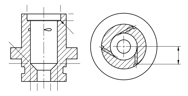
The injection of fuel into the swirl injector is done through several smaller holes. These holes are tangential to the swirl cavity inside the injector. This report explains the calculations necessary to calculate mass flow through these holes, as well as recommends a hole shape based upon currently desired mass flow of ethanol in Project X.
It is assumed that these holes for injection can be approximated the same way as straight injector holes directly into the combustion chamber.
The small size as well as the high pressures involved means that normal fluid mechanics models based on turbulent flow is not sufficient to describe the mass flow through these kind if injector holes. Instead a model based upon values gathered through experimentation is used.
Mass flow of straight holes
The mass flow of a straight injector hole can be decided using the formula in the equation below. Cd is a dimensionless constant that is decided through experiments.
$$\dot{m} = C_d A \sqrt{2 \rho \Delta P}$$
Cd can be found for some hole shapes and sizes in available literature. Linear interpolation with known values of Cd is used to find it for unknown hole sizes.
The pressure inside the swirl injector is assumed to be the same as in the combustion chamber.
Finding optimal hole diameter
To calculate the hole diameter for a desired mass flow, the above calculations for mass flow is repeated for different hole sizes. Starting at 0.5 mm diameter and increased with a step size of 0.1 mm for each calculation.
Results
The results from these calculations gives us the number of holes, as well as their shape and diameter. In the end I’ve had to restrict these calculations quite a bit. We’re limited on the shape of holes as well as the diameter by what drills we have access to. AESIR is a student organization with just a few sponsors, so drill heads isn’t exactly lying around.